Creating a Plant Layout
The AggFlow Worksheet
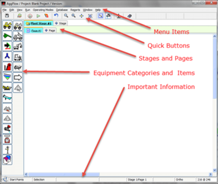
The AggFlow worksheet is simple to use. Take a few minutes to review these key areas.
Menu items
Provide essential options to manage the AggFlow worksheet.
Quick Buttons
Implement worksheet options at the click of a button.
Stages and Pages
- Add up to 4 stages to create accurate simulations.
- Link stages to each other with items from the Inventory category.
- If a stage is particularly large, add pages to expand it.
- Up to 4 pages can be added to each stage.
- Link pages to each other with items from the Transport category.
Equipment Categories and Items
The equipment categories (colored icons) contain different machine and product options. Select each category to review available options in the right column.
Worksheet Area
Create the simulation in this area.
Information Bar
Important information is displayed across the bottom of the worksheet. It will change as different items and options are selected.
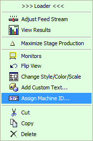
In AggFlow, left-click an item to select it (if it is on the worksheet area it will turn blue) and right-click an item to open the short-cut menu of options. Remember: Left-click to select, right-click to take action.
Manage the Flow of Material

Start Points: represent the first step in establishing the plant flow. Use start points to initiate a flow stream and to set the initial feed. Learn more: Establish the Initial Feed.

Inline Equipment: represents machines and feeders that do not alter the material. Everything that enters the equipment comes out of it without change. Examples include pan feeders and surge bins.

Transport Equipment: displays how material moves from one location to another. Examples include conveyors, haul trucks and pass-through stock piles and surge bins.

Splitters and Flop Gates: Used to manage the direction of material flow.

Inventory (temporary storage): Used to display where material resides while awaiting further processing. Inventory items are used to link one plant stage to another. Examples include surge piles and surge bins with feeders.

End Products: Conclude the material flow. Examples include product piles, rail cars, barges and product bins. Learn More: Adding End Points.
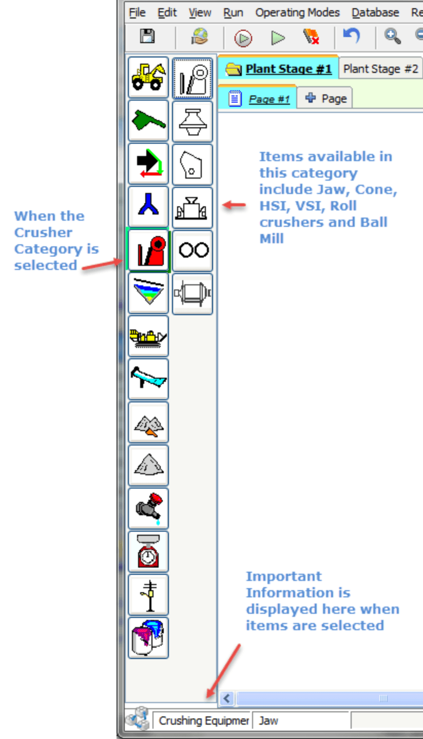
Select and Place Equipment
Two columns on the left of the worksheet provide equipment options. The left column is for Equipment Categories (colored icons) and the right column is the Equipment in that category (black and white icons) that can be used on the worksheet. When you select a category, the available equipment will appear on the right.
To Select and Place Equipment
-
Click a category icon in the left column.
The right column will change to display the equipment in that category.
-
From the right column, click the specific equipment item to be added to the worksheet.
The mouse pointer will change to a hand.
-
Click on the worksheet to place the selected equipment in the desired location.
Information about selected items is displayed in the bottom left corner of the worksheet.
Cut, Copy, Paste, Undo
AggFlow DM allows individual or multiple selections of Cut, Copy and Paste within a worksheet, to pages and stages, and to other worksheets. When equipment is copied and pasted, the setup for that equipment is also copied and pasted. If a second piece of equipment is needed or even a duplicate flow sheet, copy and paste can be used to replicate equipment in the worksheet or on another page, stage or worksheet.
- To copy the equipment, select the equipment and it turns Blue. Multiple equipment, flow lines, etc. can be selected by holding down the shift key.
- To select a window of equipment, move the pointer to the corner of the window and hold down the left mouse button and move the pointer to select all equipment in a window.
- If multiple equipment is selected, hold the pointer over one item of equipment and by holding the left mouse button down, all the equipment can be moved together.
- Multiple equipment selections can be copied or cut and pasted into other sheets.
- Undo is available to undo a placement or movement of equipment items.
Custom Text and Machine IDs
Assign custom text and Machine IDs to equipment to identify equipment in reports, and in results. Assigning equipment ID provides unique naming for modes reports, manage modes, configuration advisor and for printing reports.
Custom text and Equipment IDs are attached to the equipment and will move and copy/pasted with the equipment. Equipment IDs can be used to reflect the actual identification system used in the field.
Equipment IDs are also useful for other modules that will be added to Manage Projects.
Only the black and white icons in the right column can be placed on the worksheet. It is possible to add, delete or move (select and drag) equipment on the worksheet at any time.
Flow Streams
In AggFlow, material, slurry and water passing from one piece of equipment to another is known as a Flow Stream. Flow streams can be connected to equipment or to other flow streams.
Flow stream are used to move material from equipment to join other flow streams or to feed directly into other equipment. Equipment can only have one discharge flow stream, but multiple flow streams can feed into equipment or into other flow streams. Clicking on equipment shows the flow stream connection points. Black and blue squares are flow stream start points, and white and green squares are flow stream end points.
Equipment groups for flow steams are as follows:

This equipment is a start point shown as a black square.

This equipment has a feed connection (white square) and a single discharge (black square)

This equipment has a feed connection and multiple (i.e. 4) discharge connection points. Each discharge will need to be connected in the simulation.

This equipment has a feed connection, and is linked to another page (black square shown). The discharge will need to be started on the linked page.

This equipment has a feed connection, and is linked to another stage (black square not shown). The discharge will need to be started on the linked stage.

This equipment is an end point for material flow. It has a feed connection and no discharge.

This equipment has a feed and discharge connection and has a clean water discharge connection (blue square). The blue square can only be connected to a clean water source.

Clean water source equipment can be connected (green square) from equipment with a clean water discharge ( Blue square ). It can be connected (from blue square) to other clean water equipment and be connected to wash equipment that accepts added water.

This equipment can be connected from clean water equipment (blue square). It can be connected (from black square) to other clean water equipment and be connected to wash equipment that accepts added water.
To Start and Connect a Flow Stream
-
Select the machine or inventory item that is the starting point for the flow stream (it will turn blue).

-
Right-click the black square on the machine: A finger icon appears. This indicates that you are now creating a flow stream.
-
As you move your mouse, you will see a line that moves like a “rubber band”. This line indicates the flow stream.
-
Drag the Flow Stream to any point (piece of equipment, inventory item, product or other flow stream) on the worksheet. You will see one of these indicators:


-
When the target circle on the termination point appears, click to connect the flow stream (the direction of the mouse arrow is irrelevant). A red target indicates a connection to a piece of equipment or a product. An orange target indicates a connection to another flow stream.
-
Flow streams can be converted to slurry pipes or from slurry pipes to flow streams (see converting flow streams to slurry pipes).
-
Clean water flow streams (pipes) are only permitted for clean water flow and can only connect between equipment connections and not to other flow streams.
Flow streams appear as dashed lines until there is some material in the flow, then they convert to a solid line.
Flow lines with added water will also appear as dashed lines unless there is material in the flow
If a flow line is started unintentionally, double clicking will exit insertion of a flow line.
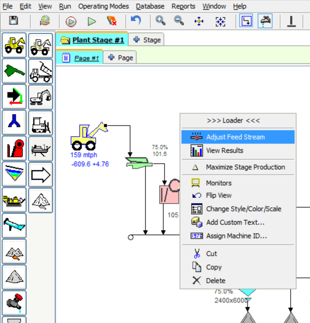
Establish the Initial Feed
The most important step in creating the simulation is to set the initial feed of material for the plant. The initial feed effects all calculations in the simulation.
- Select and place a Start Point on the worksheet.
- Select the Start Point (it will turn blue).
- Right-click and select
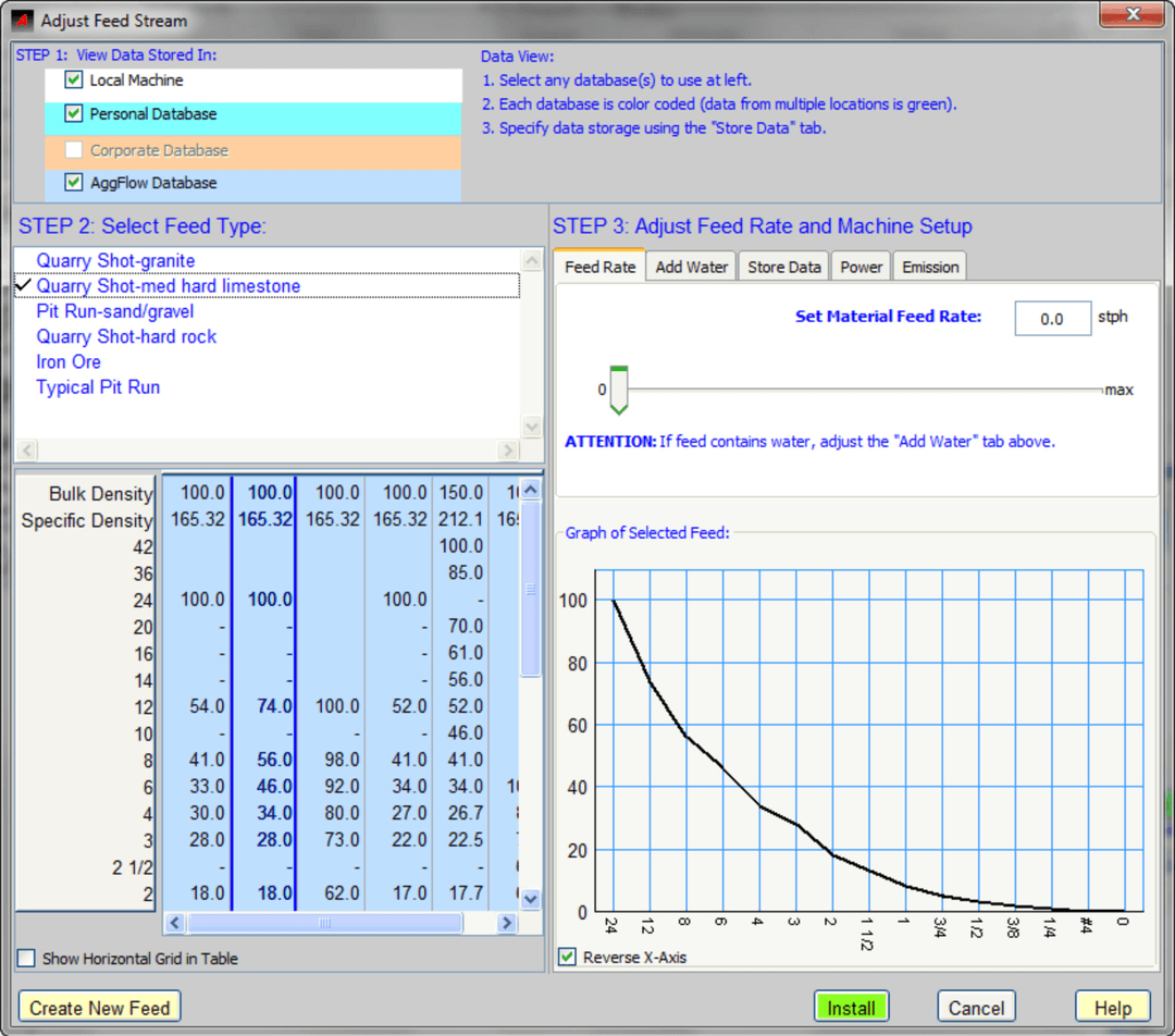
Adjust Feed Streamfrom the shortcut menu. - Follow the steps in the Adjust Feed Stream window to establish the initial feed.
- STEP 1 - Select the databases to use, each database selected will display available and saved feed gradations
- STEP 2 - Select the feed gradation by selecting a feed type and then selecting a gradation from the gradation columns
- STEP 3 - input a feed rate, and use the tabs to add water, power or set emissions.
If the actual feed gradation is known or is not available from the stored gradations, a new feed gradation can be added by clicking on Create New Feed
Learn More: Adjusting the Initial Feed Stream
The initial feed gradation is hard to measure because material sizes at this stage are typically larger than 8 inches (200 mm).
The most important factor in determining the initial feed gradation is the amount of material that passes through the first screening point.
For example, if the feed is to a grizzly feeder with a 5-inch bar opening (125 mm), then an accurate value for the percent of material passing 5 inches is required.
Orthogonal Mode
Orthogonal Mode and Bend Points can help impove the layout of your plant simulation.
To Use Orthogonal Mode
- Select the orthogonal quick button or from the
Viewmenu. - When working in Orthogonal Mode, the bottom right corner of the worksheet will display ORTHO.
- Convert an existing flow stream to Orthogonal Mode at any time:
- Select the flow stream that you want to modify (it will turn blue).
- Right-click, then choose Straighten from the shortcut menu.
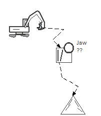
Before
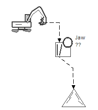
After
Bend Points
Add Bend Points While Creating a Flow Stream
The best practice is to add bend points while creating a flow stream. After starting a flow stream, simply click the location to add a bend point while the flow stream is in "rubber banding" mode (before terminating it). Every click on the worksheet will create a bend point.
Add a Bend Point to an Existing flow stream
- Select the flow stream that to modify. It will turn blue.
- Right-click the area of the flow stream where a bend point is desired.
- Select
Add Bendfrom the shortcut menu.
Straighten or Remove a Bend Point
- Select the flow stream that to modify. It will turn blue.
- Right-click the bend point that to remove.
- Select
Straighten BendorRemove Bendfrom the shortcut menu.
Learn More: Connect Equipment with Flow Streams
Multi-Stage Worksheets
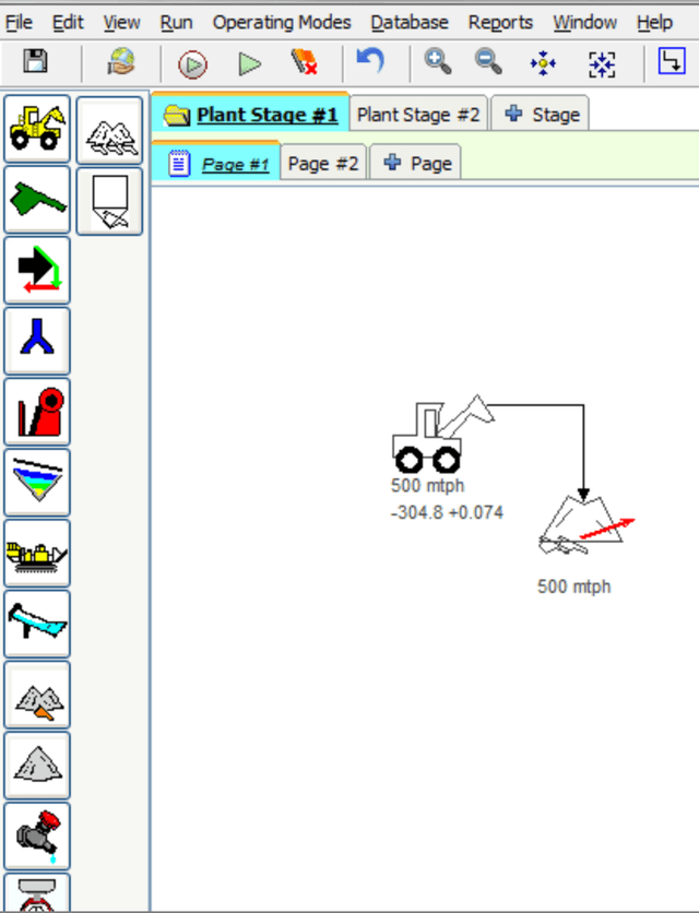
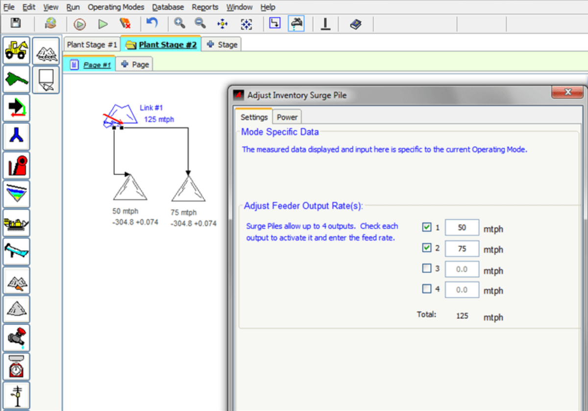
Stages are defined as a section of a plant that is divided by a surge system. A plant stage will start with a feed point and end with an Inventory Item (temporary surge). The temporary surge from one stage will connect to the next stage, and the gradation will carry to the next stage. The flow rate of the material can be changed in the next stage by adjusting the setup of the starting inventory item. The last stage ends with equipment category items End Products.
Stages are used to change the rate of flow between plant sections in a simulation. Material balance is maintained within a stage from the feed rates to inventory items or end products as the rate of material flow is calculated by AggFlow DM. The material entering all equipment and flow streams will pass through without being able to change the rate.
Feeders in a plant stage cannot be adjusted to change the flow rate within a stage.
Develop each operating stage in the simulation on a dedicated worksheet stage. Add and name each stage tab as necessary.
Important Notes About Multi-Stage Diagrams
- Add up to 6 stages to each plant.
- Only Inventory Items can be used to link stages.
- It needed, stages can be linked in both directions.
- Once created, stages can be renamed or deleted as desired.
To Add and Link Stages
-
Select the
+ Stagetab. -
Answer the “Do you want to add a stage to the plant?” question.
-
Enter the stage name and select
OK. -
Use
Inventory Itemsto link the material flow stream from one stage to another:-
Select an
Inventory itemon the worksheet. -
Right-click and select
Link To...from the short-cut menu. -
Indicate which stage to link the material flow to.
-
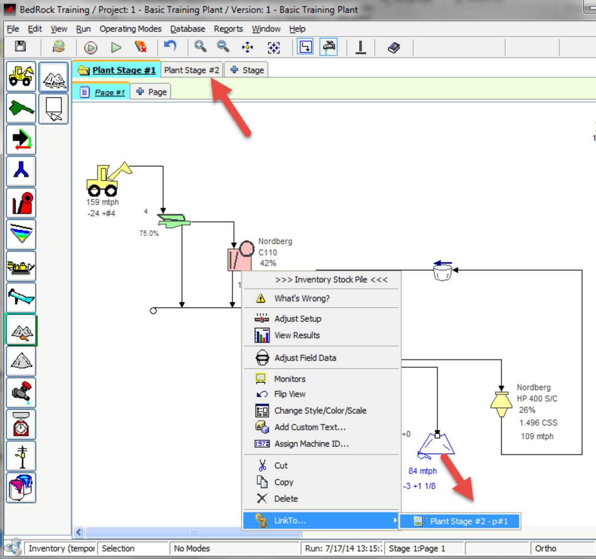
Stage and page numbers are displayed in the tabs and in the information bar at the bottom of the worksheet. Select the Link # text and right click to edit the text to wording that will help show which stage and where the link is to.
Multi-Page Worksheets
For advanced stage diagrams that are too large to fit on a single page add a page and expand it over multiple pages.
Important Notes About Multi-Page Diagrams
- Add up to 4 pages to each stage.
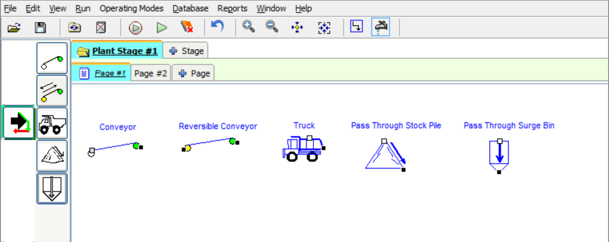
- Only Transport Equipment items can be used to link pages.
- It needed, stages can be linked in both directions.
- Once created, pages can be renamed or deleted as desired.
Transport Equipment
To Add and Link Pages
-
Select the
+ Pagetab. -
Answer the “Do you want to add a Page to the Stage?” question.
-
Enter the page name and select
OK. -
Use Transport Equipment to link the material flow stream from one page to another:
-
Select a transport equipment item on the worksheet.
-
Right-click and select Link To… from the short-cut menu.
-
Indicate which page to link the material flow to.
-
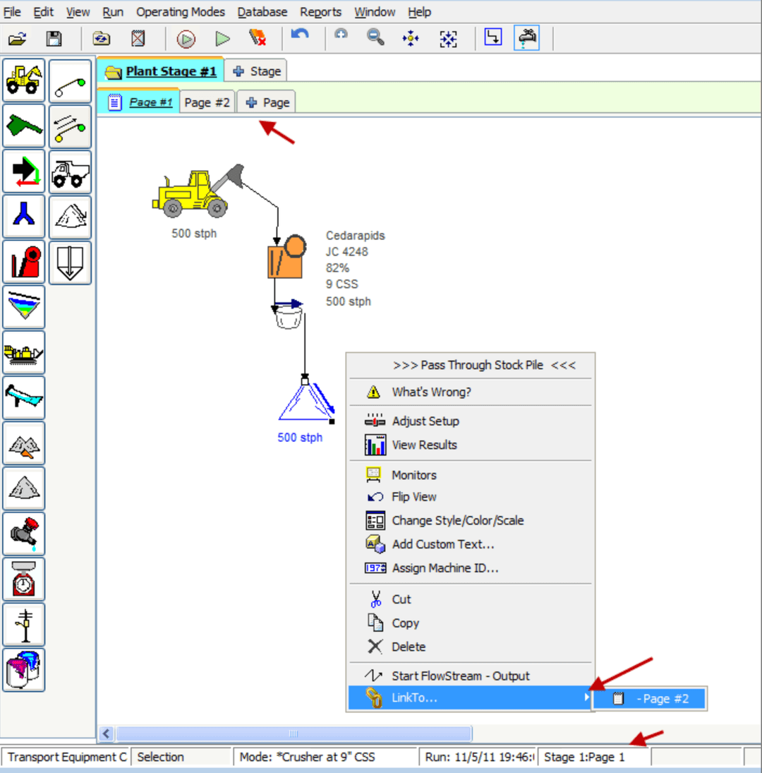
Stage and page numbers are displayed in the tabs and in the information bar at the bottom of the worksheet.